
Feature your business, services, products, events & news. Submit Website.
Breaking Top Featured Content:
Layout of Ethernet Isolators
Since I have noticed a very positive effect on the sound of several end devices through Ethernet isolators directly in front of the end devices when streaming music, I am currently working on their construction and building some myself.
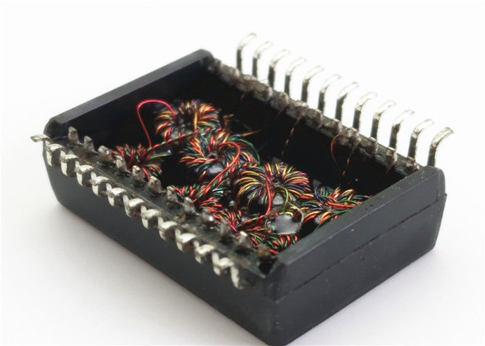
Ethernet magnetics are used for isolation, which are also used for coupling with Ethernet end devices. These usually consist of a transformer with a common mode choke behind it. This reduces noise on the line, which is noticeable in the better sound.
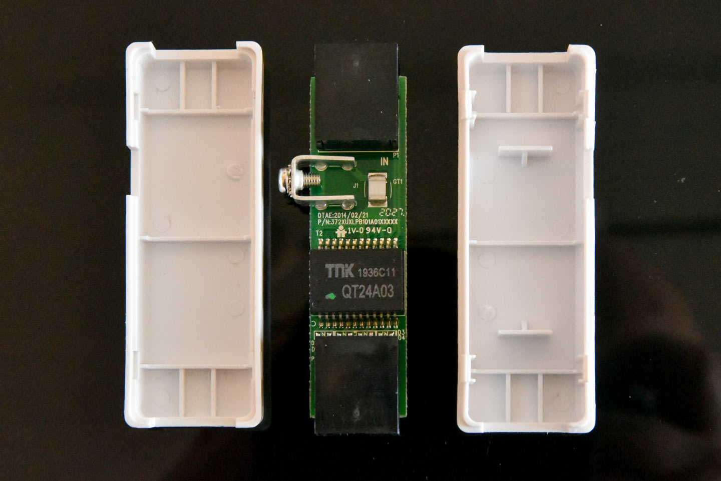
Picture of the DeLock Isolator:
Here is picture and a circuit diagram of a typical 100BaseT transformer:
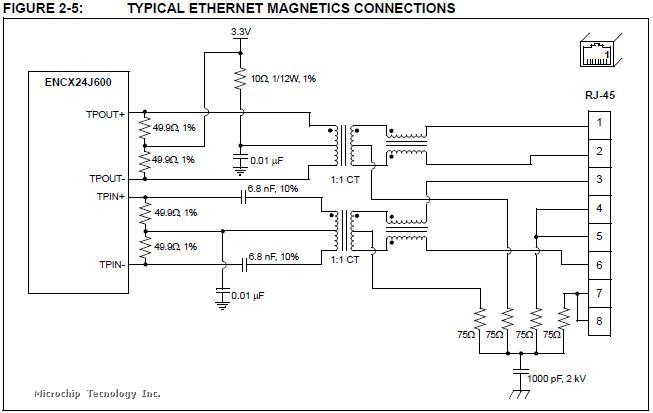
The center taps on the cable side are terminated with the Bob Smith termination: termination with 75Ohm resistor and 1000pF capacitor to ground.
The center taps on the PHY side of the transformer are integrated in the connection to the PHY.
As you can read here, the Bob Smith circuit is not without controversy: Why is Bob Smith termination for Ethernet recommended if it’s wrong? – Electrical Engineering Stack Exchange
When using the Ethernet magnetics as an isolator, it is in the middle of the cable – so it has no PHY side.
Are there any suggestions as to whether the center taps should also be terminated with bob smith termination or whether not to terminat? Should one make the termination against earth?
Would really be grateful for any input.
Best regards,
Tom.
Continue reading at DIYaudio.com: Click Here